4Square-Array for the 30m Band
Why a 4-square
The idea for this antenna originates from Les EA5AVL (SK) who built the ’40m Compact 4-Square Antenna’. A very nice concept. I decided to build a light weight 4Square-Array for the 30m Band version of it and that I would design it from scratch using EZNEC. There were constraints: all antenna components had to come from the PA3A junkbox and the array should be light weight and portable.
Short description of the array
The antenna has one radiator and 3 reflectors. All elements have the same length so to let 3 elements behave as a reflector, they need to be loaded with an inductance. This is an easy job if you know that a quarter wave transmissionline converts a capacitive reactance to inductive reactance. A brilliant idea that was was implemented in EA5AVL’s antenna. Different from the original design of connecting all reflectors to one common capacitor, I decided to connect each reflector to its own capacitor and decouple the quarterwave coaxlines with simple common mode chokes. With this concept, simulation in EZNEC is easy and turned out to give a realistic outcome.
Designing with EZNEC
So, the EZNEC homework was done. Length of all quarterwave element wires came to about 6,65m, which seems a bit short for 10 MHz but all wires are covered with 0,75mm PVC coating which has a shortening effect, and (offcourse) the verticals were placed in an array. Playing with the height of the array above groundlevel and seperation distance of the elements gave a nice insight of the possibilities but being constrained by the support structure it came down to:
– Top of antenna at about 9m
– Seperation of the wires at the top as in a 4-sqaure with sides of 3m (so 2,25m from middle support mast)
– Seperation of the feedpoints at about 3,5m from the middle support mast (as a 4-square with 5m sides)
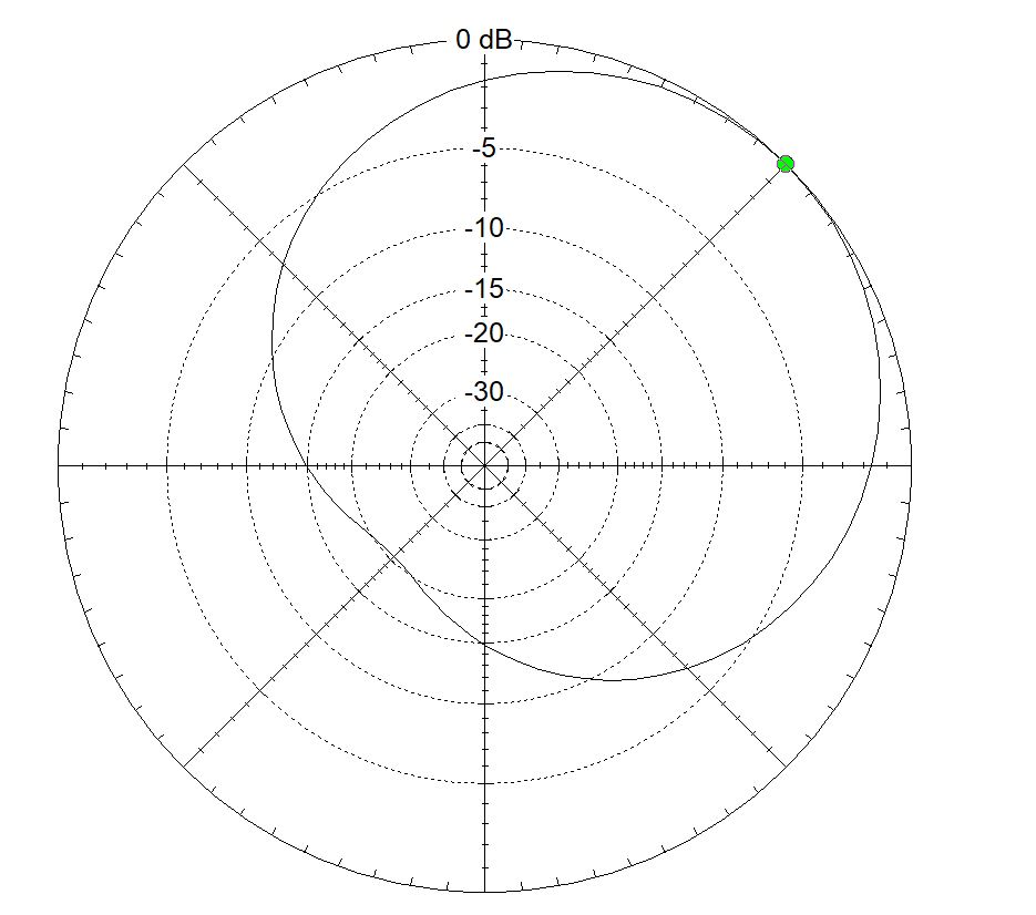
The EZNEC prediction was about 3dB gain over a single groundplane antenna and a F/B ratio of 15-20 dB for modest elevation angles (see the pictures). SWR would turn out to be about 1 : 1.3 at resonance. And after building and testing, I could conclude that this was a very accurate prediction! Never been so close to reality with EZNEC.
The actual build
Components of the contraption:
– 12m vertical of Spiderbeam (set to about 9m)
– PVC pipe spreaders and supports
– A spreader ’thing’ made by Mart PH0MH (snug fit for PVC pipes)
– Loudspeaker feeder cable as antenna wire
– 1/4 wave 50 ohm RG-58CU coax feed each element, so 4 feeders (length about 4,88m)
– All elements connected to a capacitor of 440 pF (= 2 x 220 pF) through a 1/4 wave coax
– CAT-6 cable to switch the relay box
– Switching relays in the box are capable of handling 16A – 240V. They were donated by Henk PA3D
– The switchbox is at the center. A deactivated relay connects the 1/4 wave feeder to the 440pF cap. If one relay is activated, it switches one element (the radiator) to the transmitter coax, the other three elements stay connected to their 440 pF caps and act as reflectors.
For demonstration of the F/B ratio I recorded the audio from my Elecraft K3 monitoring a 30m QSO of LY2PX. It is in the youtube video below.
EZNEC Data
The EZNEC file can be downloaded here: ![]() PA3A 30m 4 Vertical Array
PA3A 30m 4 Vertical Array
For info on EZNEC: https://www.eznec.com/
Click on the pictures/photo’s for better view.

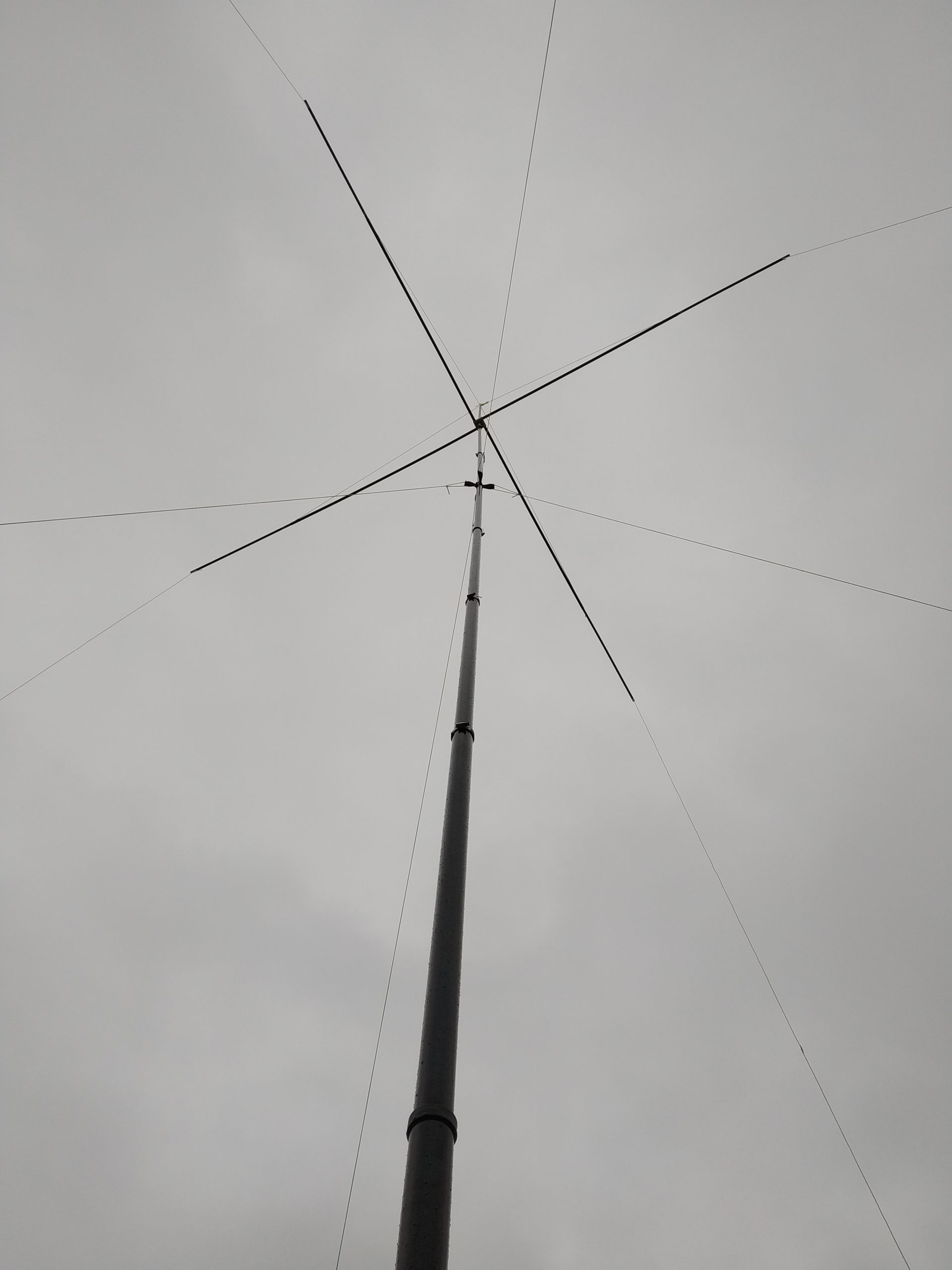
The 4 Vertical Array erected
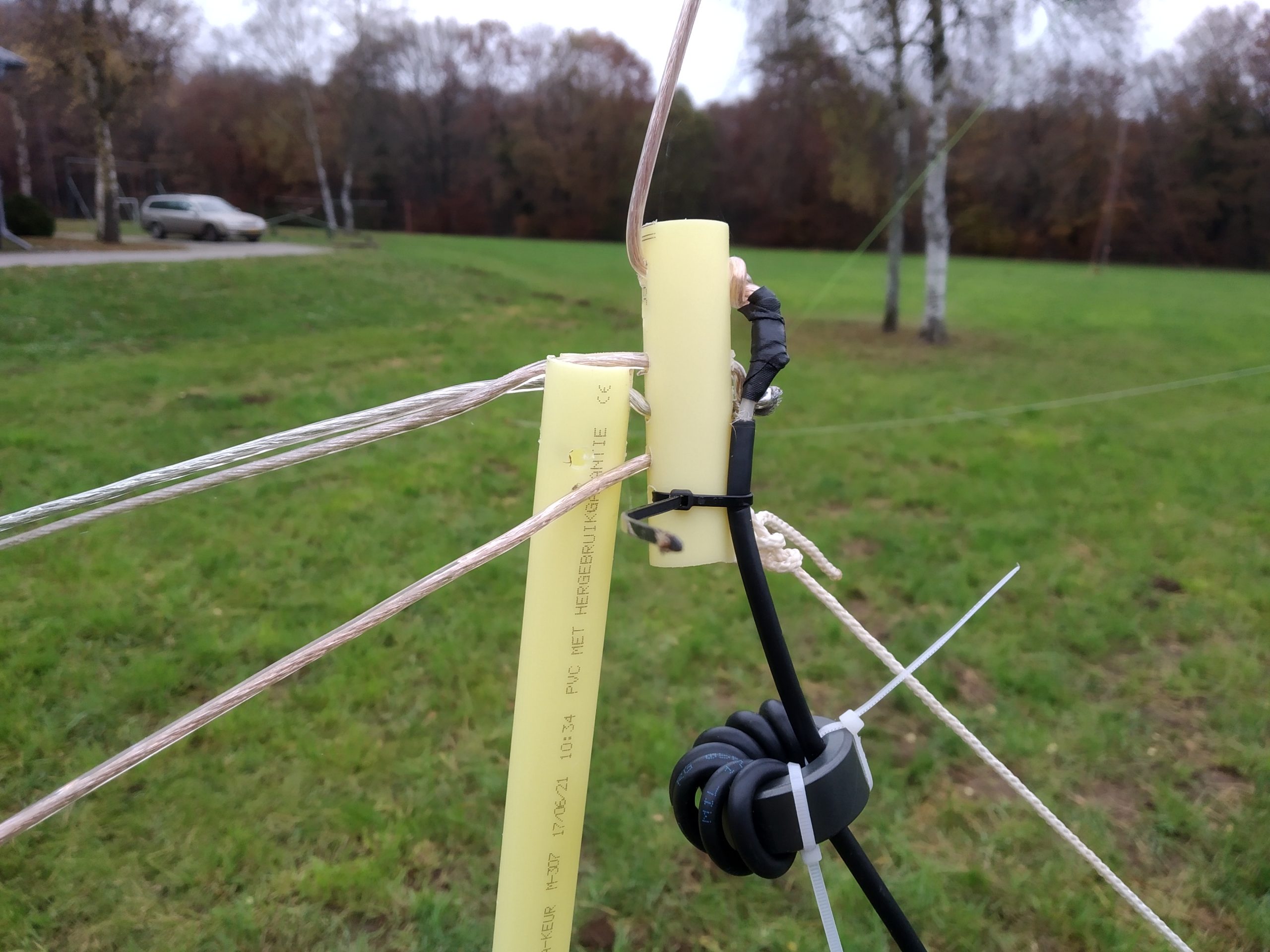
Top spreader

Antenna Top Support

Spreader ’thing’
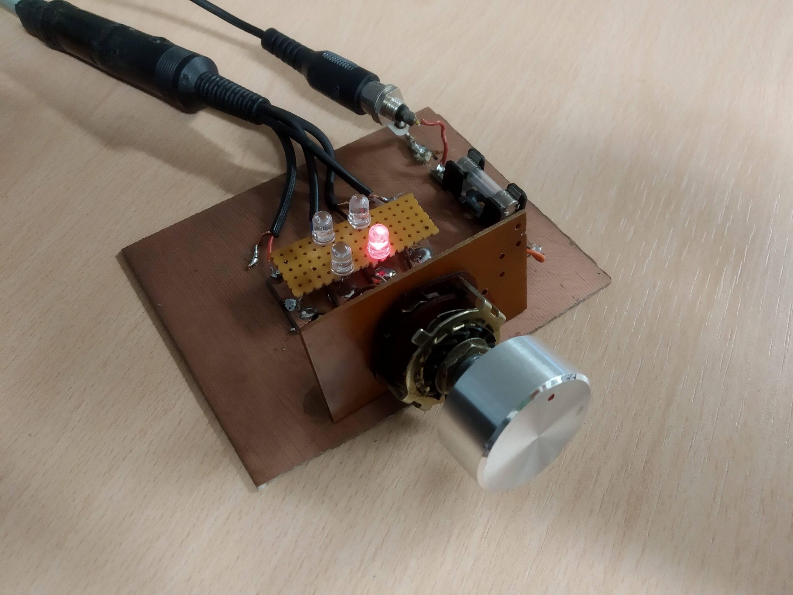
Switch with active LED Direction indicator
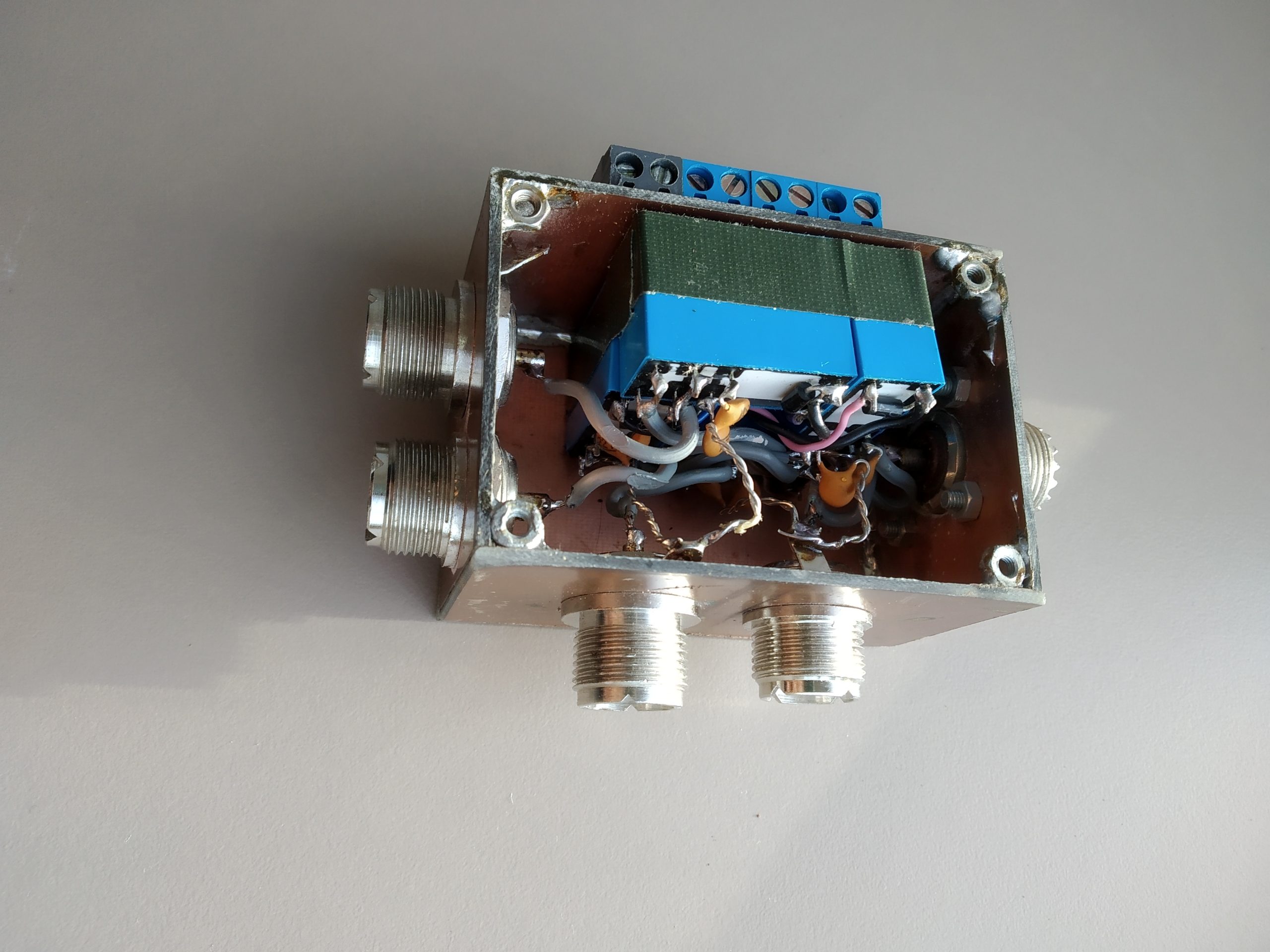
Relay Box, all relays 16A 240V

Relaybox in use
Coax Feeder with Common Mode Choke
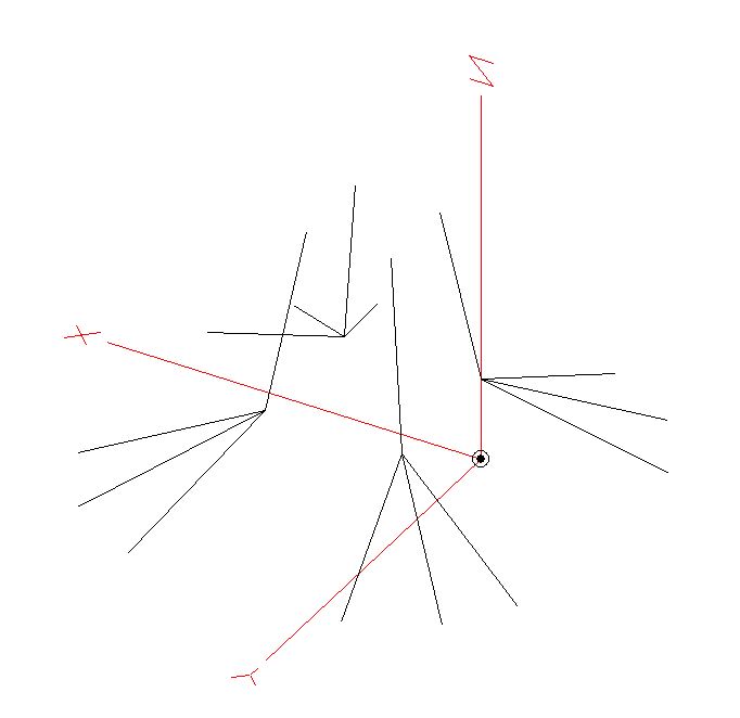
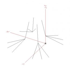
EZNEC antenna design

EZNEC 3D plot
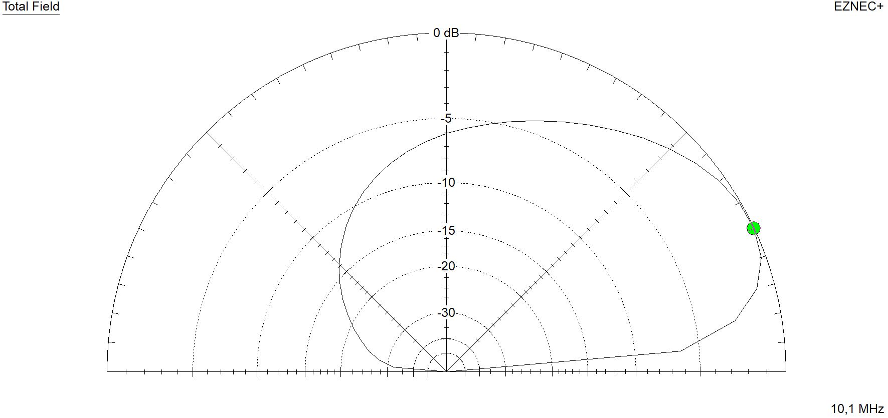
EZNEC 2D elevation